A novel tested technology for cooling electronic circuitry is available, also useful in many other industries. The method is called “Thin Cavity Fluidic Heat Exchanger”, abbreviated TCFHE. Technology details can be viewed at the U.S. Patent and Trademark website, application 20100078155.
The TCFHE is a simply constructed, small volume, high performance, and effective method for cooling critical electronic devices at the chip, board, module, and system levels. Its high thermal performance originates from a very high velocity air flow, a very thin boundary layer, and high air utilization. It can efficiently and reliably cool critical regions in electronics at very low cost, in a small space, with high design flexibility, and with no concern for air leakage causing damage. The TCFHE resolves the conflict in high speed electronics to completely seal a compact enclosure for shielding and packaging purposes while also removing high heat loads. It is technically positioned between fan and heat sink methods and water cooling methods of cooling. When fan and heat sink methods or packaging constraints cannot obtain the needed thermal performance, the TCFHE is the next best choice over water cooling.
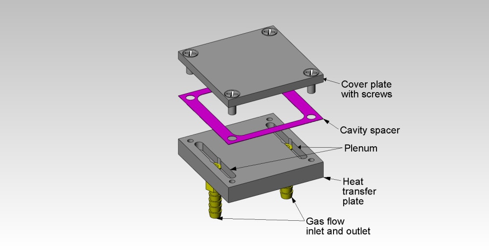
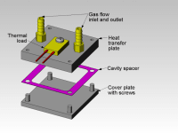
Cross-sections for a basic TCFHE for a simple planar structure are shown. It consists of a thermal load, heat transfer plate, a cavity spacer, a cover plate, a gas inlet, and a gas outlet. The cavity spacer can be a feature of the heat transfer plate or the cover plate instead of a separate item. Heat produced by the thermal load is conducted to a heat transfer plate, which can be planar, tubular, or another shape. Compressed air or other gas passes by the plate through a thin gap (able from a micro to macro scale in power generation and distribution, defense, automotive, electronic, chemical, biomedical, and other industries. TCFHE structures can be used for air conditioning, refrigeration, combustion heaters, engines, motors, transformers, lighting, supercomputers, telecom, server farms, integrated circuits, and other devices. Building infrastructure capital and energy costs can be reduced when such products are used, due to remote location of the gas flow source and heat exhaust. The gas used could be air, nitrogen, oxygen, Freon, or similar gases at hot, room, or cold temperatures and can be direct or alternating pressure. It could be hot gas produced by internal or external fuel combustion or cool Freon gas from refrigeration systems. The gas flow could originate from a gas compressor, compressed gas tank, ducted fan or blower, combustion chamber, or other pneumatic source. The technology also works well with liquids.
-
Awards
-
 2012 Top 100 Entries
Like this entry?
-
About the Entrant
- Name:Steve Morra
- Type of entry:individual
- Software used for this entry:Solidworks
- Patent status:pending


