


Proposal for a Solar Tracking System for the Solar Panels of a Satellite, Adopting the form of the tested Solar Locating and Tracking System Model named “Heliotropio Stefanides”
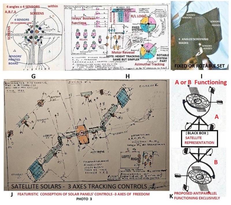
PHOTO 3 J , SHOWS THE PROPOSED SYSTEM FOR CONTROLLING THE SATELLITES SOLAR PANRLS FUNCTIONING INDEPENDENTLY BUT EXCLUSIVELY AND PHOTO 3K IS A FEATURISTIC CONSEPT FOR SOLAR PANELS’ SOLAR TRACKING BY A 3-AXES CONTROL SYSTEM.
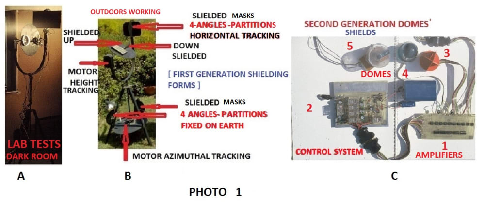
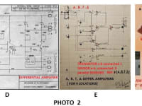
The proposal here, The Model of a Solar Locating and Tracking System named “HELIOTROPIO STEFANIDES [ PHOTO 1] is proposed here as such one, as it has been tested functioning according to design, with originally involved corrections, for problems of interferences from reflections. The originally built Tracker device, tested in a dark lab and due to reflection problems unveiled under the full sun outdoors, used to search appropriate solutions for designs of sensors/amplifiers and control [ C 2] system [ differential amplifiers C 1], with filters for noises of reflection interferences and also devising better homing for sensors within shielded partitions/masks or specially devised domes [ C 3, 4, 5 ] caring at the same time for their appropriate dimensions for obtaining more accurate results. Born in hands, for long periods and sessions, the device of PHOTO 2 F, was used for variable conditions of Insolations. Redesigned sensor amplifiers, resulted in obtaining special prototype differential amplifiers [PHOTO 2 D, E, F] and appropriate housings within shielded partition masks [PHOTO 3 G, I] or domes [PHOTO 1 C 3,4,5 ], choosing the appropriate dimensions for homing sensors within appropriate Plastic or Glass Domes [ Photo 1 C 3, 4, 5]. Reflections filtering for the “Solar Locating and Tracking System” which originally involved Photocells and later Quadrant Photodiodes [Morririca]. Testings of such light Maskings for functioning well [ approx. 1.5 deg error], lasted for many hour session over many months.
PHOTO 3 G shows locations of 4 sensors in each of the 4 angles. Three of them are required for filtering reflected signals of the involved radiation and cutoff actions of the sensors within angles other than the one searched for the direct radiation. PHOTO 3 H demonstrates the originally conceived control system. It involved relays for the Boolean Logic, DC Motors [ 2], simple Transistor Amplifiers and Photocell Sensors.
The sets of combinations minimize to the following “AND” functions: CLOCKWISE ROTATION: Α.Α’, Α.Β’, Α.Δ’, B.A’, B.B’, Γ.Β’ - ANTICLOCKWISE ROTATION: Α.Γ’, Β.Γ’, Β.Δ’, Γ.Α’, Γ.Γ’, Γ.Δ’, - STOP: Β’. Γ’ or Δ [Night Region 90 deg as assumption here for the design conditions. The AZIMUTHIAL reciprocation is assumed 270 deg for SUN- RISE /SUNSET in summer [for Greece it is about 222 deg]. The vertical [ALTITUDINAL] reciprocation BEGINS when the AZIMUTHIAL STOPS. Functions here are simple [up and down reciprocation 90 deg]. Other combinations [erratic which may, indeed, occur] beyond specified, are considered incompatible and bring the system to total STOP, until Self Rectification. Indication of 2 consecutive angles in the “ON” State indicates the direction [Azimuthally] lying between the 2 angles. Any form of temporal interference brings system to stop, until interference problem resolves.
Refferences
- http://www.stefanides.gr/Pdf/HELIOTROPIO.pdf
- http://www.stefanides.gr/Pdf/SENSORS_93_TECHNICAL_CHAMBER_OF_GREECE_PANAGIOTIS_STEFANIDES.pdf
- http://www.stefanides.gr/Pdf/SENSORS_93_TECHNICAL_CHAMBER_OF_GREECE_PANAGIOTIS_STEFANIDES.pdf
- http://www.stefanides.gr/Pdf/HELIOTROPIO.pdf
https://youtu.be/2nF3ZLqcCSo
http://www.stefanides.gr
Video
Like this entry?
-
About the Entrant
- Name:Panagiotis Stefanides
- Type of entry:individual
- Patent status:none