

Present technology for cooling a piston throughout the entire engine operating range is to supply crankcase oil for cooling through the piston oil nozzle assembly explicitly to satisfy the worst case engine operating conditions. Unnecessary high pumping power is required to circulate the engine oil used for cooling. The oil flow is constant for any given engine rpm and not load dependent. Moreover, if the engine is not operated at a 100% load condition, resultant excessive cooling to the piston dome underside will result in overcooling the piston dome which contributes to elevated soot levels in the crankcase oil and exhaust.
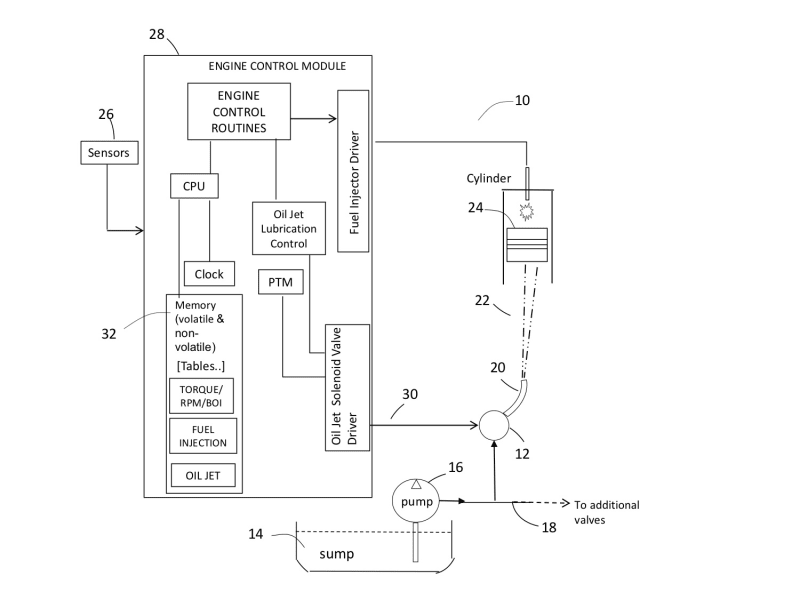
Illustration 1 satisfies these aforementioned needs by a patented piston dome cooling system 10, is comprised in one aspect, of pulse-width-modulated (pwm) solenoid valve 12, wherein, lubrication oil from the oil sump 14 is pumped by the oil pump 16 through a common rail manifold 18, through valve 12 to spray nozzle 20. One spray nozzle is generally utilized per cylinder and, oil spray quantity 22 is illustrated in this embodiment, with a reduced modulated quantity of spray, preferably directed below the piston dome 24. The motivation for this invention is to base the amount of oil used in cooling/lubrication, to the amount of thermal loading imposed on the piston due to increased loading and, perform it in a closed loop manner. The amount of oil delivered to the spray nozzle 20 shall be a function of engine feedback parameters read by sensors block 26 of engine controller 28 and a resultant pulse width command signal 30 based on look-up table(s) 32. In particular, the pulse width duty cycle signal shall modulate the valve 12 anywhere in the range of 0% to 100%, wherein, 0% represents a shut off valve (no oil flow) and 100% is fully open (max power).
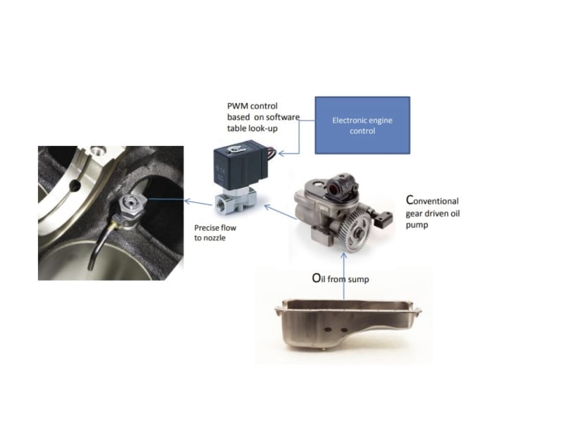
Illustration 2 depicts a conventional gear driven oil pump used on a diesel engine with an oil routing path through the inlet port of a pwm solenoid valve and, the outlet port directed to an oil jet nozzle or tube, wherein, the oil nozzle is directed to the piston dome underside to cool the piston and the piston liner.
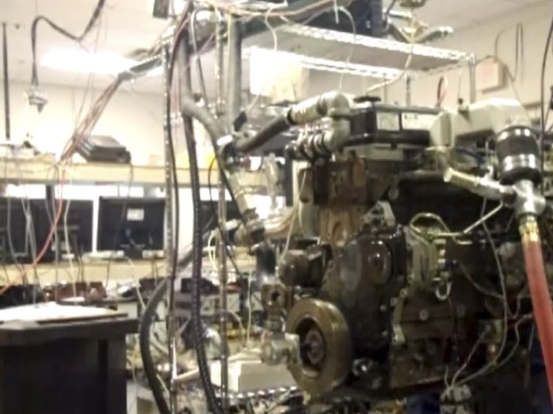
Illustration 3 is a photo of a Dodge-Cummins 5.9L, I-6 diesel engine modified for single cylinder operation, used to successfully complete a small Phase 1 Government Grant. The initial results of testing this “proof of concept” oil jet control, demonstrated a substantial improvement in emissions.
- Allows for longer intervals between oil changes (less soot build up)
- Accommodates the use of duel fuels
- Allows for rapid warm-up in cold climates resulting in reduced emissions
- Shall work on the majority of OEM and retrofitted diesel engines, including military, marine, mining, construction, locomotives, gen sets, light/med/heavy duty trucks, off-road trucks
- Provides for reduced soot and ash entering the particulate trap, wherein, trap life is extended
- Provides a new path in meeting the stringent 2024, 2027 EPA Emission regulations, further extending the viability of the “diesel engine workhorse”
-
Awards
-
 2022 Automotive/Transportation Honorable Mention
 -
 2022 Top 100 Entries
 -
 2022 Top 10 Most Popular
Like this entry?
-
About the Entrant
- Name:Michael Holihan
- Type of entry:teamTeam members:Michael J. Holihan (co-inventor)
Patrick J. Derbin (named inventor) - Software used for this entry:prototype hardware/software
- Patent status:patented


