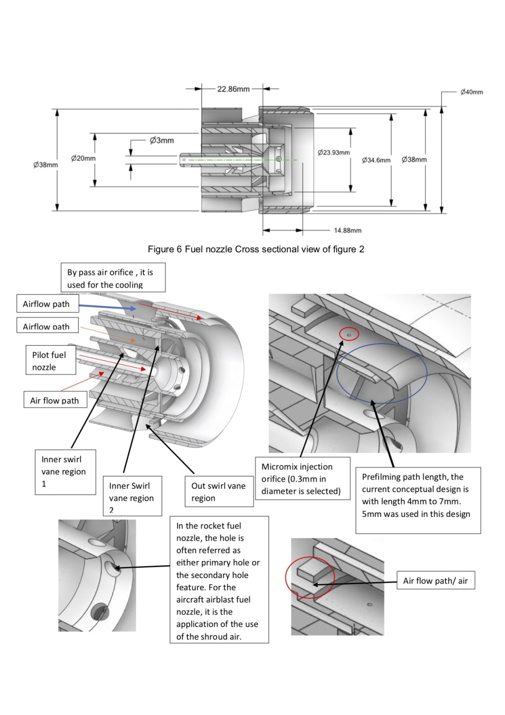
The airblast fuel nozzle is a critically important element that decided the fuel atomisation quality. The droplet size determined the evaporation rate and the combustion efficiency, and pollution formation. LDI configuration is defined as a simplex airblast fuel nozzle with the flare modification in the conventional lean direct injection design. The flare feature can be separated from the simple flare or the complex flare. The main concept is the blended LDI concept and the micro mix fuel injector concept in this conceptual design. The overall length of the main part of the fuel nozzle is 42mm. The major ratio of the chamber length and the orifice were calculated based on the single LDI. The ratio of the chamber length and the orifice were applied in this triple swirl vane design and decide on the initial position for the swirl vanes. In the existing literature resource, the prefimling path length can be varied from a very small value to a relatively greater value. In this design, the prefilming path is selected with 4mm. The reason for adding the prefilming path is beneficial of the atomisation quality and reduce the droplet size.
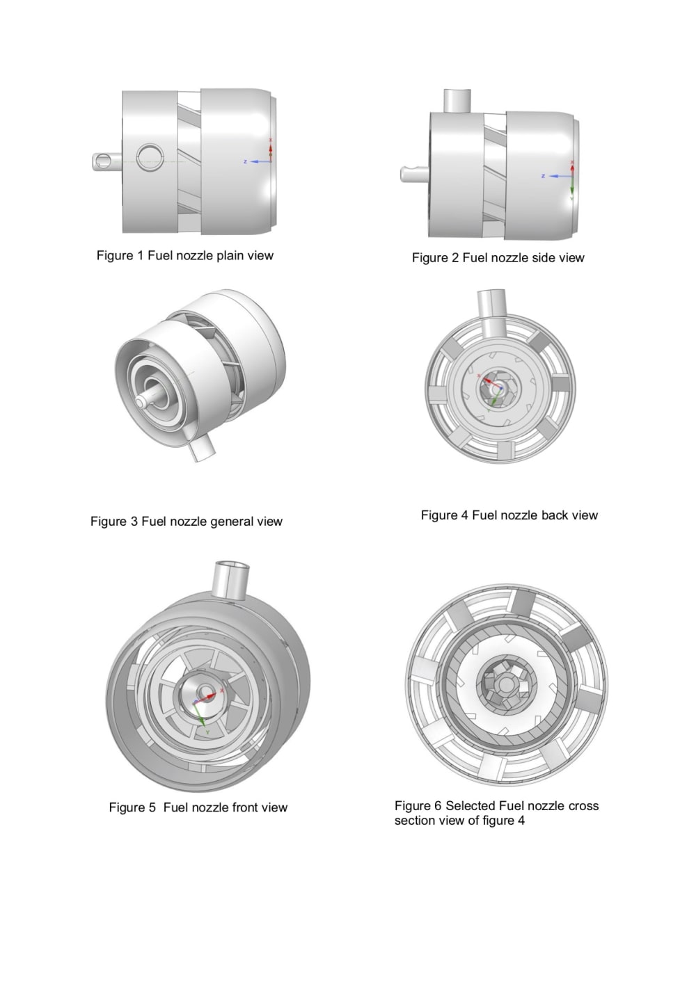
Minimise the frequency oscillation compare to the non prefilming airblast fuel nozzle. The design concept also used the dual fuel concept. The conceptual of the pilot fuel injection and the secondary fuel injection. However, the concept is slightly different from the conventional duplex fuel nozzle because this concept is main for the airblast type. It is designed with the air shroud feature for rapid fuel air mixing before enter the combustion chamber. The upper micro mix fuel injection orifice diameter was 0.3mm; the swirling air is passed through the air guide orifice and the upper air guide path. At the end of the fuel nozzle lip, there is an extra design feature for cooling purposes with conduct bypass through an annulus orifice. Currently, 20 micro mix injection holes were calculated from the upper deck fuel injection blockage factor. 10 prefilming micro mix injections were applied at the bottom deck fuel injection region. The detail can be found in the pictures in the next section. The annular fuel flow path is designed with a small annular diameter to prevent fuel coking. The fuel nozzle design is a complex process. Thus, this conceptual design has provided a large capacity for improvement and optimisation. Which it is one of the common design requirement with ease of upgrade and optimisation. There are two documents uploaded in the next section; the detail and the major feature of the design can be found.
Like this entry?
-
About the Entrant
- Name:Zhengda Li
- Type of entry:individual
- Software used for this entry:Ansys Spaceclaim
- Patent status:none


