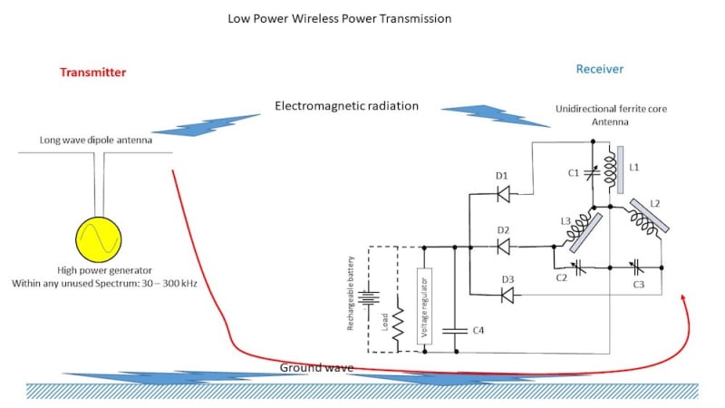
Most of the commercially available wireless power transmitters or chargers use short range magnetic coupling. Non resonant coupling is usable only within a few centimeter range. The resonant coupling results in a little longer range. As the distance grows in-between the transmitter and receiver, the efficiency drops. There are capacitive coupling transmitters as well; these also suffer from same problem. However, it is possible to transmit power wirelessly over a long distance if we use electromagnetic radiation. Long wave radio frequency (30 – 300 kHz) is not in use now for broadcasting news and entertainment programs much, as it requires a large antenna for radiation and high static noise. However, long wave can travel long distances by the process called ground wave propagation. Attenuation for ground waves at long wave is much less than that for medium wave or short wave. If every after 200 km Transmitters of few hundred kW are placed, wide area can be covered for wireless power transmission. Within a few km radius of a transmitting antenna, power could be obtained at the receiver varies from few Watts to several mW. At the fringes (10's of km) power could be few mW to microwatt level. Tough the power level is low through this process, however this power could be sufficient to power up and charging many devices, like clocks, low power medical devices, mobile phones etc. Though for efficient radiation at long wavelength large antenna is needed, however at the receiving end small ferrite rod antenna is sufficient to grab power. To make the power reception unidirectional, several ferrite rod antennae oriented in different directions can be used. As the power transmission can be done at a single frequency, the tuning is simple, the variable capacitors once tuned at the transmission frequency can be maintained at the same position. The obtained power is detected by diodes and a capacitor (could be a super-capacitor) is charged. A voltage regulator can be used to make sure the desired level of voltage never exceeds, when the receiver is to close to the transmitter. The whole idea is expressed in the block diagram.
Like this entry?
-
About the Entrant
- Name:Sajjad Haidar
- Type of entry:individual
- Patent status:none

