My entry solves problems common to most engines including the attainment of high efficiency, simplicity, ease of manufacture, use of multiple fuels, reduction in weight, and the number of parts.
The benefits of my engine are many, utilizing renewable energy, reducing the depletion of fossil fuel and the carbon footprint. It would be a “green” engine.
My entry is based upon my book “The Most Efficient Engine” (ISBN10) #1441464392 and my patent number US 8,683,797 B1, which requires novelty, such as the reduction of heat loss by the strategic disposition of low heat transfer materials, confining most of the heat transfer to and from the working fluid of the engine, and preset dimensional relationships between the various parts of the engine to assure proper temperatures of the working fluid relative to the temperatures of the heating and cooling elements.
There are many applications for my engine. Consider the trend toward “green” energy. There are solar power plants being built, utilizing Stirling engines driven by the heat of the sun. My engine would be superior to a Stirling engine, which requires regenerators. Another application is space power. Heat from solar, geothermal, ocean thermal energy, nuclear energy, and fossil fuels could power my engine, which could drive an electrical generator.
The worldwide market potential would be huge. Increasing population creates a thirst for clean power production.
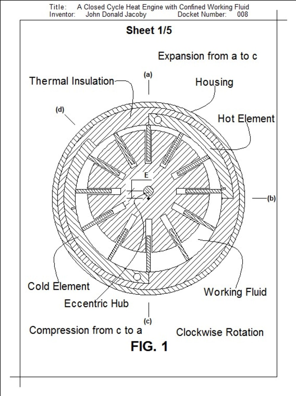
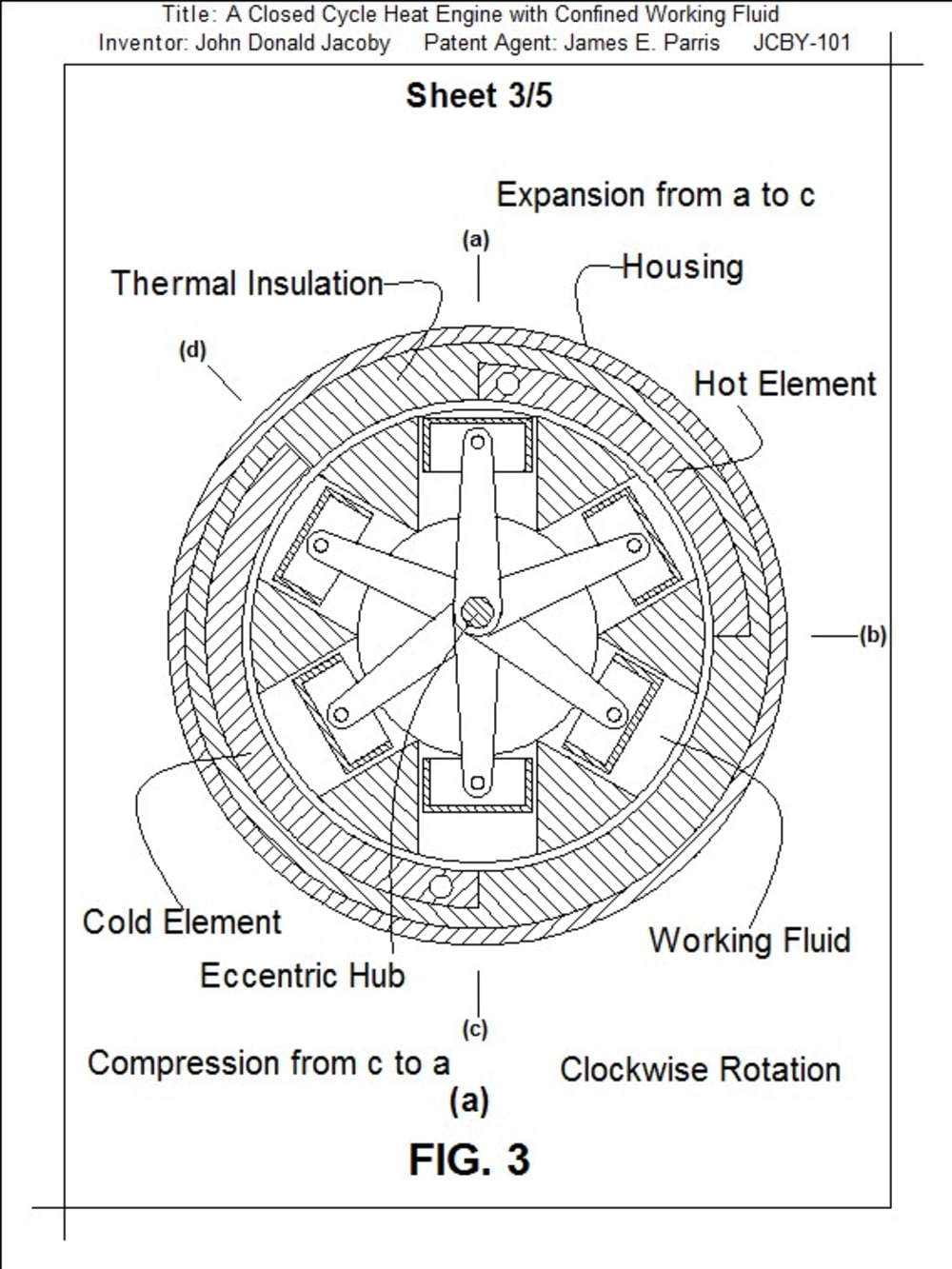
My engine operates on a closed cycle utilizing a working fluid, which performs work, while receiving heat at a high temperature from a higher temperature heating element during expansion, and absorbing a portion of that work while rejecting heat at a low temperature to a lower temperature cooling element during compression, the net work being available to power an external device. Its dimensions are tailored to provide the proper temperature parameters. The amount of working fluid and rotor eccentricity control the power of the engine.
The engine manufacture would use conventional machining methods.
Production cost would be less than similar engines because of simplicity.
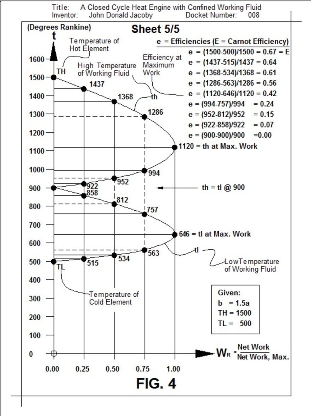
The illustrations are simplified from my patent, showing two variations of my engine and a graph depicting TH of the heating element, TL of the cooling element, th and tl, the high and low temperatures of the working fluid, b, a, and Wr, respectively the cooling area, the heating area, and the relative work, with e being the efficiency at various working fluid temperatures. Other graphs are available for variations of the temperatures TH and TL. For example, TH could equal 660° Rankine (200° F) and TL could equal 500° Rankine (40° F).
The graph shows efficiency, e, varying from zero to the Carnot efficiency, E, and relative work, Wr, varying from zero to a maximum.
Pristine equations in my book are the bases for my graphs, patent, and engine. They derive the famous Carnot efficiency, E=1-(TL/TH), without using reversible processes and validate the equation, e=1-Sqr(TL/TH), the widely quoted Novikov equation for efficiency at maximum power, as well as giving broader insight into heat engine operation. For book and patent, see JAKESV.COM.
Like this entry?
-
About the Entrant
- Name:John Jacoby
- Type of entry:individual
- Software used for this entry:DesignCad3D Max
- Patent status:patented


