


My design is of an aircraft named LA-95, which is constructed from an alloy of Lithium and Aluminum and has a double turbo fan system, along with Pratt and Whitney F119 engine network. Below mentioned, in detail are some of the changes designed which are developed differently from other jet engines to enable faster means of travel.
Compression Chamber :-
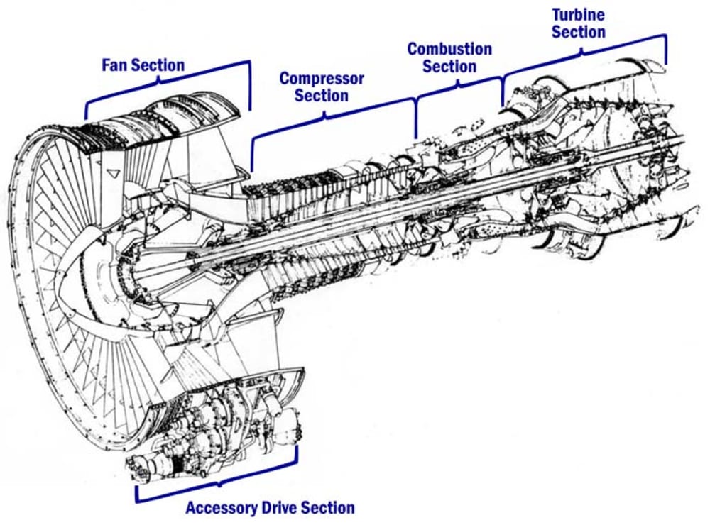
In most passenger aircraft the turbojet is an air breathing jet engine, usually used in aircraft. It consists of a gas turbine with a propelling nozzle. The gas turbine has an air inlet, a compressor, a combustion chamber, and a turbine (that drives the compressor). The compressed air from the compressor is heated by the fuel in the combustion chamber and then allowed to expand through the turbine with a propelling nozzle. However, in my design LA-95, the compression chamber is going to be larger than in the average engines. This will cause the turbines to rotate at a much higher speed adding more energy to the airflow, in a specific area. The pressure ratio will be around 8:1. In most of the jets of modern era, there are two separately rotating parts. However, LA-95 consists of four parts for aerodynamic improvements, incorporating variable blade angles for entry guide vanes and bleeding air from the compressor.
Combustion Chamber :-
Before discussing the combustion chamber in LA-95, let’s first take the piston engine into consideration. In a piston engine the burning gases are confined to a small volume and, as the fuel burns, the pressure increases. In my design of the aircraft the air and fuel mixture burn in the combustor and pass through to the turbine in a continuous flowing process with no pressure build-up. Instead there is a small pressure loss in the combustor. The fuel-air mixture can only burn in slow moving air so an area of reverse flow is maintained by the fuel nozzles for the approximately stoichiometric burning in the primary zone. Further compressor air is introduced which completes the combustion process and reduces the temperature of the combustion products to a level which the turbine can accept.
Thrust:-
Since, the combustion chamber and the compression chamber have a larger area, so it’s an innovative thought to use the thrust mechanism used in Air Force jets. The thrust-to-weight ratio and wing loading are the two most important parameters in determining the performance of an aircraft. For example, the thrust-to-weight ratio of a combat aircraft is a good indicator of the maneuverability of the aircraft. The thrust-to-weight ratio varies continually during a flight. Thrust varies with throttle setting, airspeed, altitude and air temperature. Weight varies with fuel burn and changes of payload. For aircraft, the quoted thrust-to-weight ratio is often the maximum static thrust at sea-level divided by the maximum takeoff weight. In cruising flight, the thrust-to-weight ratio of an aircraft is the inverse of the lift-to-drag ratio because thrust is the inverse of drag, and weight is the inverse of lift
Like this entry?
-
About the Entrant
- Name:Shah Mir Aizaz
- Type of entry:individual
- Software used for this entry:Microsoft Office Tools.
- Patent status:none