The idea of new type of heat engine (called Heat Pipe Engine, HPE, hereafter) is derived from pressure variation inside the heat pipe vessel in its operation. Significant feature of HPE is that its thermodynamic cycle is theoretically close to Carnot cycle performed in liquid-vapor two-phase region of pure fluid which corresponds to the region surrounded both by saturated-liquid and saturated-vapor lines on the thermodynamic-chart of fluid.
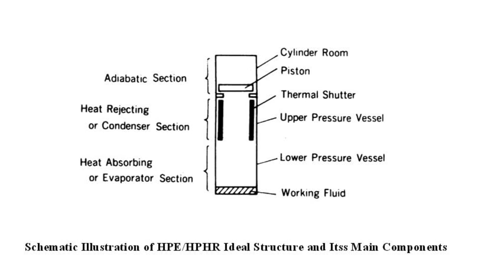
The structural configuration of HPE is quite simple; an evacuated cylindrical vessel having a piston to receive pressure and a thermal-shutter to create pressure variation inside the vessel, as schematically shown in Fig.1. The upper-half of the vessel is exposed to low temperature heat source (heat rejecting section), and the lower half is to high temperature (heat absorbing section). The piston is located on the top of the vessel, and the thermal-shutter is a wide hollow inner-ring structure made of thermally adiabatic material which moves up and down along the inner side-wall of the vessel. The role of thermal-shutter is to open/close heat rejection area (upper part of vessel) periodically to reduce/increase the vapor pressure in the vessel, while the vapor is constantly generated at the bottom of the vessel. This thermal-shutter is characteristic to HPE system, as it consumes little energy in its movement. Letting the thermal-shutter move in different cycle phase to that of piston approximately 90 degrees, work (or power) is continuously taken out. The working fluid is chosen so that it makes phase change in the temperature range of applied energy.
It should be noted, as thermodynamic theory states, that HPE system works as an effective heat rejecting system (or cooler) when operating its cycle movement in adverse way in the proper working condition, as schematically shown in Fig. 2 (in blue color). We name this device a Heat Pipe Heat Rejecter (HPHR), but skip the details here.
Significant features of HPE (and also HPHR) are as follows. Firstly any heat sources of low temperature and/or density energies like waste heat from factories, solar heat, geothermal energy and others are applicable to this device. Secondly, the device is relatively easy to manufacture owing to its simple structural configuration, and it can be settled anywhere as long as energy sources of two different temperature levels are available. Thirdly, as thermodynamic theory conceives, HPE thermodynamic efficiency is apparently quite low since we try to make good use of waste heat energies that are otherwise discarded as useless. Evaluation of thermal efficiency on HPE should be a different story.
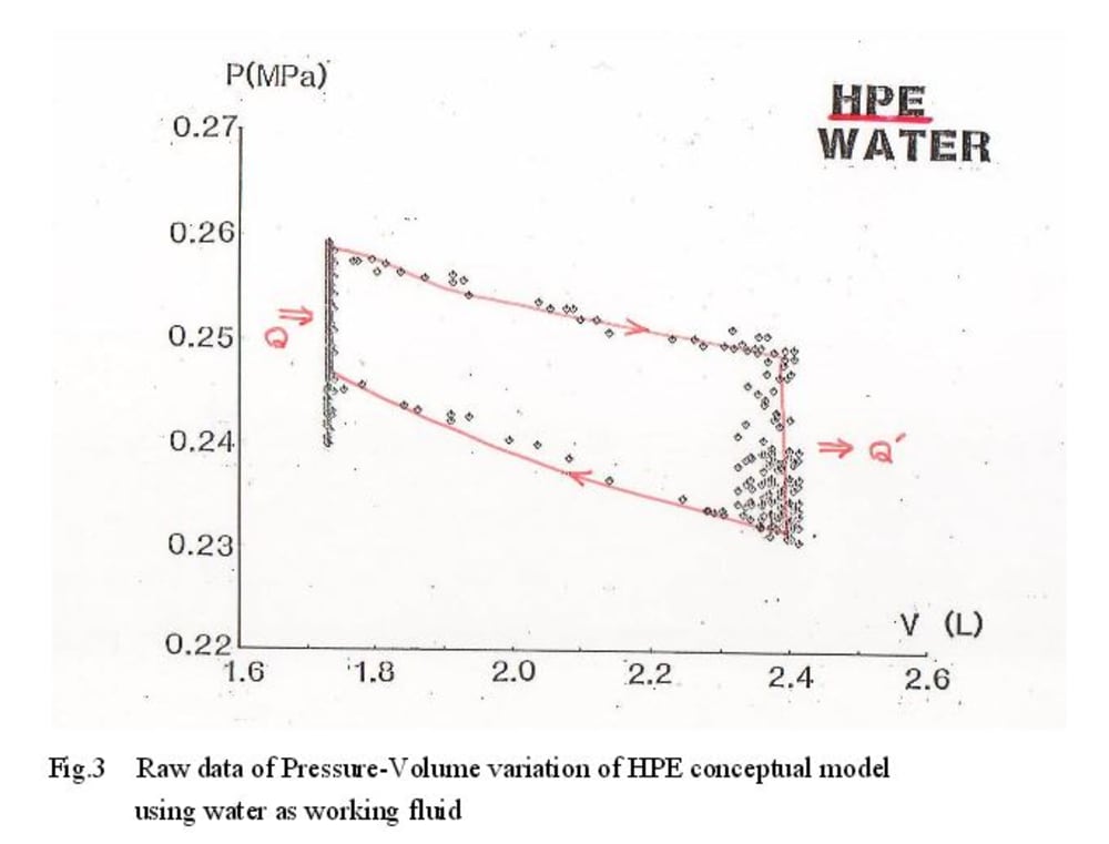
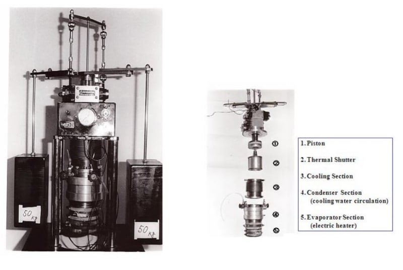
We have manufactured conceptual HPE (HPHR also) models, operated them, and confirmed that they work as we have anticipated. The external view and main components inside HPE are illustrated in Fig. 2, and video is available. One of the typical data of practical thermodynamic cycle (P-V diagram) taken is shown in Fig.3. The main body of approximately 12 cm bore by 30 long cylindrical vessel functioned in 15 rpm with lifting 100 kg weight up-and-down, generating power of 30 W.
Like this entry?
-
About the Entrant
- Name:Kobayashi Yasunori
- Type of entry:individual
- Software used for this entry:N/A
- Patent status:none


