Introduction
Today’s world is concerned about the depletion of natural resources and the impact of human activity on the environment. Making automotive transportation more efficient is one of the major goals of engineering research. Ideas in unconventional areas tend to be economically and technologically untested while internal combustion engines still hold significant unrealized potential.
Current limitations
Variable valve timing and lift solutions have been widely employed to gain efficiency. However, existing devices and methods have several limitations, including restricted ranges of adjustments of valve stroke and inability to deactivate valves in the process of engine operation within one revolution of the camshaft. These limitations negatively impact volumetric efficiency, energy conversion efficiency, specific fuel consumption, and exhaust toxicity. Existing mechanisms of cylinder deactivation only work with fixed groups of cylinders and create complications such as thermal imbalances, uneven wear, and unstable transition regimes.
Proposed solution
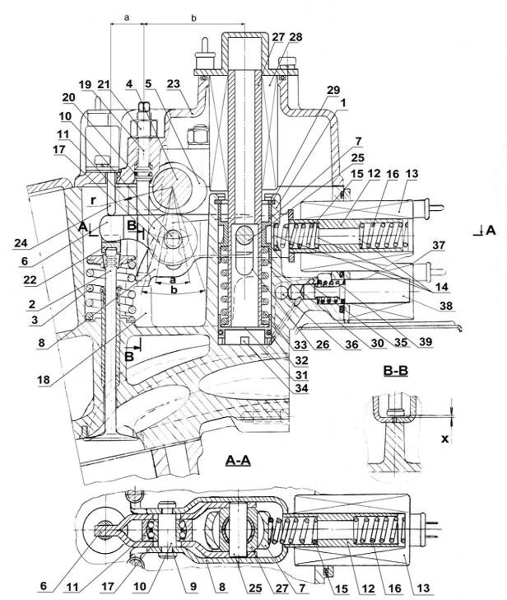
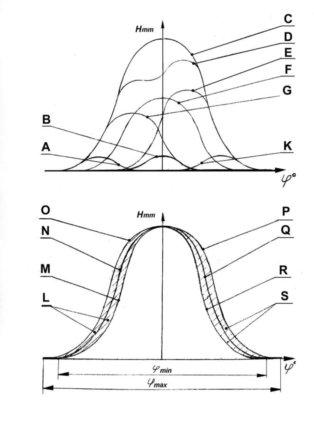
The presented electronically controlled hydro-electrical mechanism of valve lift and valve timing regulation with flexible cylinder deactivation solves or reduces the above problems by employing a principle of the balance scale: a valve spring on one end acts against a hydro-electrical system on the other end through a lever and a floating fulcrum. This device allows adjustments of both valve lift and timing, deactivation of valves in one or several cylinders, and alterations in the order and number of working cylinders. Starting, idling, partial/full load regimes are optimized from a continuous range of relationships between valve timing and lift and all possible algorithms of cylinder activation. Valves can be opened and closed two-three times during one stroke. The transition from one regime to another happens during one or four strokes, depending on crankshaft rotation speed. Valve opening duration can be adjusted by narrowing the range at low engine speeds and widening it as the engine speed increases, keeping maximum valve lift or lowering it. Application of this invention would bring significant improvements in engine efficiency, elasticity, and toxicity without sacrificing maximum attainable power and torque. The curve of specific fuel consumption is lowered and straightened in the entire range of engine’s operation. The solution can be implemented through existing economically viable technologies. The global annual market value of engines equipped with the device can reach $50-100bln.
Technical abstract
The device consists of camshaft (4) with cams (5), lever-pusher (6) with movable bracket (8), core pin (27), electromagnet (28) of valve stroke, guide (7) of valve drive, controlling hydro-cylinder (30), and electromagnet (13) of valve timing regulation. Lever-pusher (6) contains roller (11) kinematically connected with cam (5). Movable bracket (8) is coupled with core rod (12) of electromagnet (13). Lever-pusher (6) acts on valve (2) and is connected with guide (7) via fulcrum pin (25). Fulcrum pin (25) is located in a through slot (26) of core-rod (27). Guide (7) is installed in controlling hydro-cylinder (30). Core pin (27) rests on piston (31) of controlling hydro-cylinder (30). Spring (33) is installed between guide (7) and core pin (27).
Diagrams provide examples of achievable lift/timing functions.
-
Awards
-
 2012 Top 100 Entries
Like this entry?
-
About the Entrant
- Name:Yury Kostyukovich
- Type of entry:individual
- Software used for this entry:none
- Patent status:patented


