Changes in intake and exhaust valve timing and throw directly effect the power, torque and fuel efficiency of a four stroke Internal Combustion Engine (ICE). The timing (or phase) relative to the position of the piston alters when the valve begins to open or close during an intake or exhaust stroke while the throw (or eccentricity) determines how quickly the valve opens and closes (the Lift Rate), how long the valve is off of its seat (the Duration), and the maximum available throat area when the valve is fully opened (the Valve Lift). Additionally, the intake and exhaust valves have a phase relationship between when each is at its maximum lift -- called the Valve Phasing or Overlap -- which also has an impact upon power, torque and fuel efficiency.
Historically, ICE cams have been designed with fixed parameters, and a variety of prototypes produced with differing characteristics. Empirical data was then collected from engines equipped with the different prototypes and the performances compared to determine and select the best option for a particular production run. Once produced these cams had specific, unchangeable characteristics considered the best options for a particular goal.
If high performance is desired, the cam is "ground" to provide maximum lift and duration where the most horsepower would be obtained, sacrificing fuel efficiency and any possibility of smooth running at idle. If high fuel efficiency was the goal, the cam was manufactured appropriately, resulting in milder performance, but smoother idle.
Both high performance and high fuel economy could be achieved if the timing and throw of the valves could be adjusted, especially if the exhaust and intake valves could be controlled independently. This dynamic adjustment of both timing and throw is now possible with an application of the Angular Motion Translator (AMT), the subject of U.S. Patent 6,547,689.
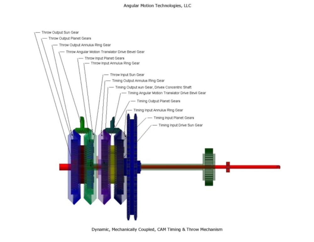
In Image 1 (a 3D PDF file), two Angular Motion Translator assemblies are installed on a pair of concentric output shafts. The inner shaft is connected to a gear that will adjust the maximum eccentricity (or throw) of a valve cam while the cam is in motion. The outer shaft is driven by a separate AMT, which controls the timing of the cam. When the Timing Drive Bevel Gear is rotated, the change in angular relationship between the two annulus rings is added to the motion of the drive sprocket, changing the timing of the outer shaft relative to the drive sprocket. When the Throw Bevel Gear is rotated, motion is added to the inner shaft, rotating the attached gear.
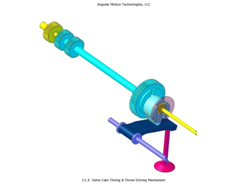
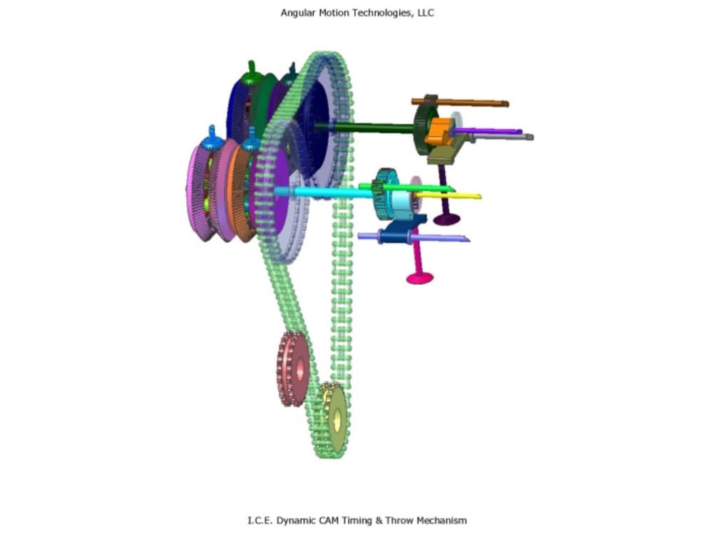
Image 2 shows the two AMT mechanisms with their output shafts attached to a cam drive assembly and a cam. Image 3 shows the entire assembly with two paired drive mechanisms, one for the intake valve drive train, one for the output valve drive train.
With the assembly shown in these images, the timing (Phase) and throw (Eccentricity) of the valves can be directly controlled, with completely mechanical couplings, while the engine is running.
Like this entry?
-
About the Entrant
- Name:Paul Baker
- Type of entry:individual
- Software used for this entry:AutoCAD ADT, Alibre Design Expert
- Patent status:patented


