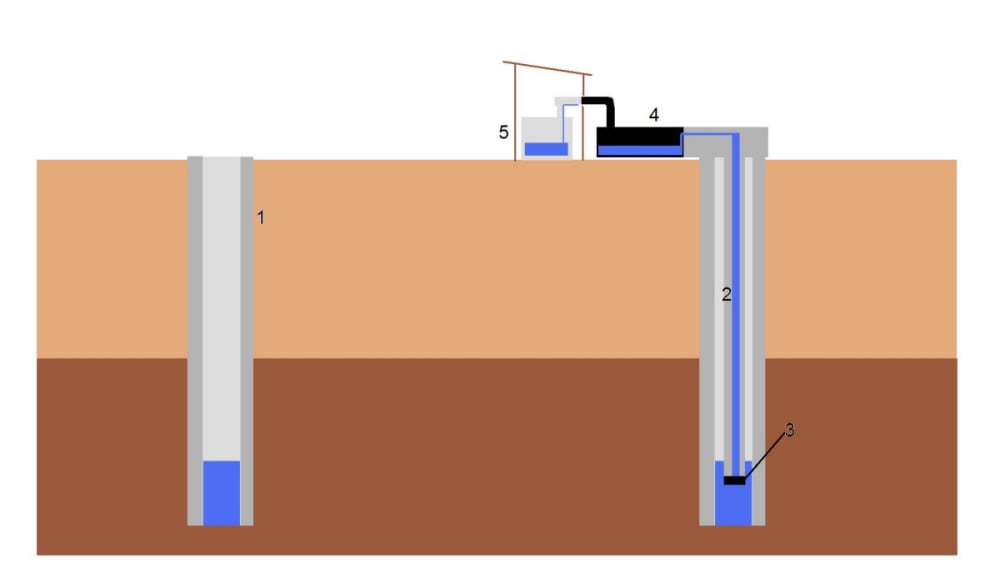
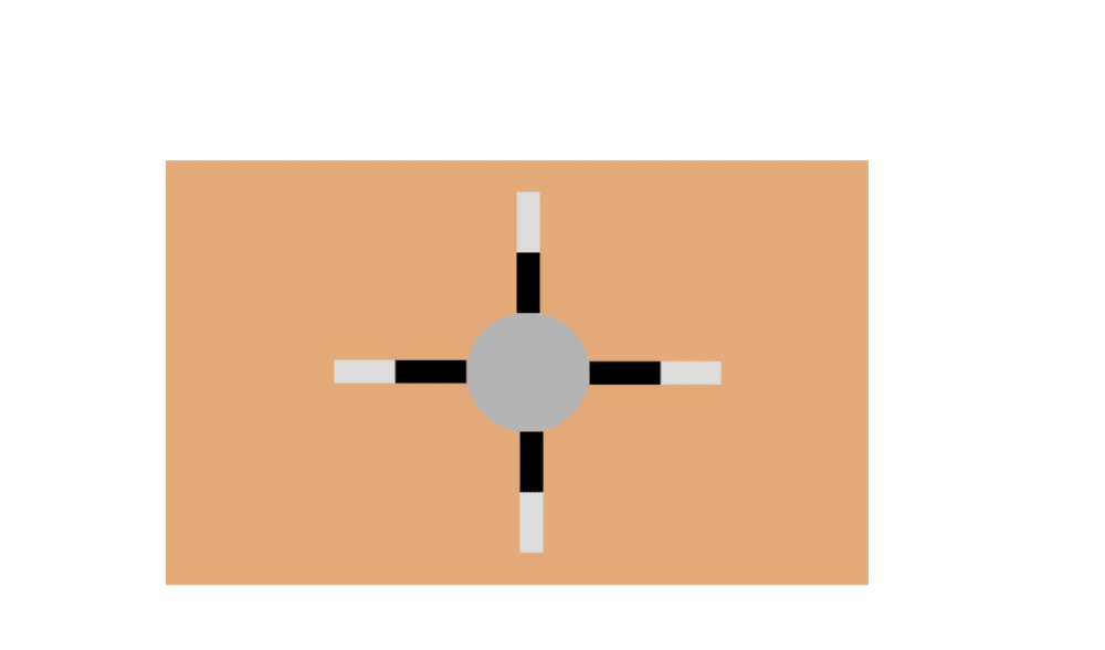
The Osmotic well consists of the following parts numbered on the figure. 1.outer casing 2.inner casing 3.semi permeable membrane 4.Black holding tank with shut off valve 5.Bright storage tank Once the well is dug and water located, a second casing is lowered into the water. At the end of the casing a semi-permeable membrane is attached. This allows for water to pass but not large molecules. Inside the second casing a small amount of water is placed together with salt. This will initiate the osmotic process. With current technology used for extracting hydro electricity, this can produce water pressure equivalent to a 120 meter water column. http://www.statkraft.com/energy-sources/osmotic-power This means the process can also elevate water by 120 meters. As the water reaches the top, it flows into a black holding tank. This water is salt- water and needs to be distilled before it is drinkable. Once the holding tank is full, a valve system similar to that in a toilet closes the tank. The water evaporates from the black tank and condensates into a bright colored storage tank placed in the shade. Once enough water is transferred to the storage tank, the valve in the holding tank opens a feedback line to the well allowing the salted solution (now more concentrated) back into the well while opening the holding tank to be re- filled. The returning of the salt will increase the amount of salt in the well and keep the osmotic process running. The reason for making the second casing is for when the membrane must be changed. The casing allows for extracting the membrane without spilling salted water into the base of the well which would weaken the potential of the process. The Osmotic process will be faster than the evaporation process. To increase the speed several tanks can be connected to a single well.
Like this entry?
-
About the Entrant
- Name:Carsten Haavardtun
- Type of entry:individual
- Software used for this entry:Paint
- Patent status:none


