The idea to utilize waves in elastic solids for generating rotational motion goes back to Sashida (1982) and has become widespread in mechatronic systems, for instance in photo cameras for focusing the lenses.
The basic idea behind the so called travelling-wave-type-motor are the elliptic trajectories of the surface points in the stator. The wave crests in contact with the rotor are producing a directed friction force making the rotor move. Thus the energy is converted twice. First electrical energy is converted into mechanical in terms of high-frequency vibration, which is subsequently converted again by a frictional contact in kinetic energy of a planar motion.
The advantages of this kind of motors are manifold. They offer high positioning resolution, compact size,
large power density, high torque at low speed, high stationary limiting torque when switched off and absence of electromagnetic radiation. Furthermore, no lubrication is needed, which predestines these motors for applications under vacuum atmosphere.
The success of the rotational motors gave rise to investigations about linear motors which are the object of current research, e.g. Feenstra (2005).
The focusing and steering of elastic waves has been studied in the context of structural health monitoring, e.g. by Giurgiutiu (2007). Therefore the principles from active phased radar from antenna theory served as model.
Conflating these ideas culminates in a motor with three degrees of freedom (x,y,phi) which brings the advantages of ultrasonic motors to micromechanical systems. Particular advantageous is the rotor positioning in x- and y-direction and rotating simultaneously, avoiding position error accumulation, as it happens for sequential placement.
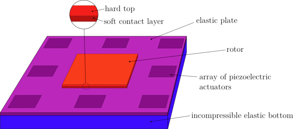
Figure 1 illustrates schematically the construction of the motor.
The stator is a plate made of an elastic material, e.g. a metallic alloy or synthetics.
The bedding of the plate in rubberlike, incompressible, low-density cushions
prevents static deflecting while letting the waves pass. The piezoelectric actuator arrays are placed in the fringe of the plate, around the operating area.
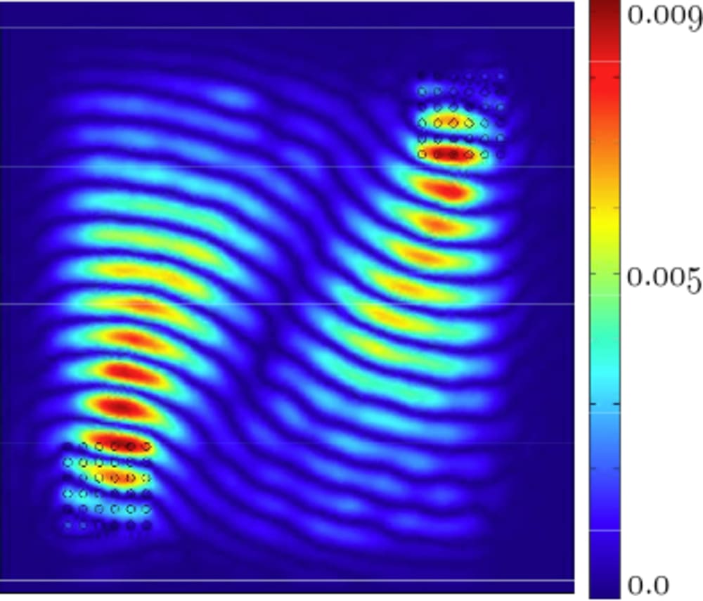
They are either used as sources for generating the waves or as sinks for actively damping out the waves in order to minimize reflections. As an example figure 2 shows the wave field generated to make the rotor turn.
The rotor, particularly its contact layer, should fulfill certain tribological requirements in order to obtain a high efficiency. In all likelihood this concept should also work for any solid object to be transported without special contact layer and potentially for granular media and liquids.
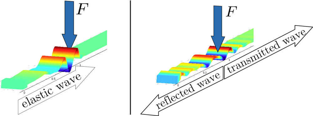
Moreover from the reflections due to the contact forces, which are visible in figure 3, the position of the rotor can be detected. As the actuator arrays allow the precise shaping of the beam, they can be used conversely for the reconstruction of the contact area, i.e. its shape and position. Therefore the sensor signal needs to be extracted from the actuators by the means of self-sensing circuits.
Like this entry?
-
About the Entrant
- Name:Dominik Kern
- Type of entry:teamTeam members:Georg Jehle, Dominik Kern
- Hardware used for this entry:DESKTOP PCSoftware used for this entry:MATLAB, COMSOL
- Patent status:none


